Products
Hydraulic Power Packs
Function:
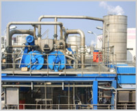
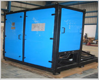
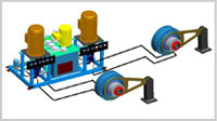
A complete hydraulic drive system from SCHRODER HYDRAULICS Drives comprises the Power unit with electric motor, pump and tank, the control system, the hydraulic motor and the piping system. The power unit type HPU is described in this publication and uses a closed loop hydraulic system to provide a highly dynamic drive system. We have expertise to build custom built hydraulic power units.
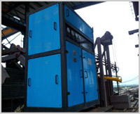
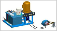
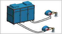
In most offerings, all items except the piping and hydraulic motor are housed in a sound insulated cabinet. The swash plate pump is driven by an electric motor running efficiently at fixed speed.
The oil flow from the pump is determined by the swash-plate angle, which is controlled by a signal from the control system. Starting in an unloaded, neutral condition, the system ramps the flow up to the required direction and rate and pressure is determined by the load up to the limit set at the compensator. If pressure reaches compensator setting the pump will destroke, stopping the drive, so eliminating heat buildup but maintaining the set pressure and therefore torque at the drive. The pump will stay in this condition until the system is unloaded where upon the pump will immediately ramp up to the set Flow rate or until the control is adjusted. The pump and the hydraulic motor are connected together by flexible hoses and piping if necessary.
At the motor the oil is distributed through the valve plate to the pistons in the cylinder block 50% of them with high pressure and 50% with charge pressure. The oil pressure forces the piston assemblies radially outwards against the cam-ring. This produces a balanced and smooth rotation with extremely high torque which drives the machine. The speed of the motor is controlled by the flow of oil from the pump. Drive motor speed is therefore proportional to the swash plate angle of the pump.If the swash plate is controlled over-centre, the flow is reversed and the motor direction is therefore reversed.
Both the hydraulic motor and the pump have a very low moment of inertia, which makes it possible to change speed and stop or reverse direction quickly.
A proportion of the return flow is used to provide oil conditioning by cooling and filtering. The oil in the motor and pump case which provides lubrication and local cooling is fed back to tank via an adequately sized drain line.
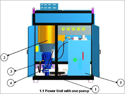
MAIN COMPONENTS:
2.ELECTRICMOTOR: An electric motor is an electromechanical device that converts electrical energy into mechanical energy. The electric motors that we use have high efficiency and are also extremely reliable. They are started with no load and run optimally at fixed speed.
3.SERVO FILTER: The oil filters are dimensioned for oils with high viscosity and a high degree of contamination separation. Servo filter can be supplied as an option, allowing you to replace filters during operation.
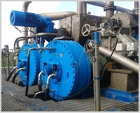
4. PUMP: The hydraulic pumps are of the variable displacement axial piston type with very fast acting pressure compensator override. This virtually eliminates overloads and is a major factor in system reliability. All control valves are built in to keep pipe work to an absolute minimum. The electro-hydraulic stroke provides variable flow by smoothly controlling the swash plate and there by pumps displacement.
DIMENSIONS:
Power Unit With One Pump:
Features of the HPU Power Unit
INCLUDED AS STANDARDS
A complete hydraulic drive system from SCHRODER HYDRAULICS Drives comprises the Power unit with electric motor, pump and tank, the control system, the hydraulic motor and the piping system. The power unit type HPU is described in this publication and uses a closed loop hydraulic system to provide a highly dynamic drive system. We have expertise to build custom built hydraulic power units.
In most offerings, all items except the piping and hydraulic motor are housed in a sound insulated cabinet. The swash plate pump is driven by an electric motor running efficiently at fixed speed.
The oil flow from the pump is determined by the swash-plate angle, which is controlled by a signal from the control system. Starting in an unloaded, neutral condition, the system ramps the flow up to the required direction and rate and pressure is determined by the load up to the limit set at the compensator. If pressure reaches compensator setting the pump will destroke, stopping the drive, so eliminating heat buildup but maintaining the set pressure and therefore torque at the drive. The pump will stay in this condition until the system is unloaded where upon the pump will immediately ramp up to the set Flow rate or until the control is adjusted. The pump and the hydraulic motor are connected together by flexible hoses and piping if necessary.
At the motor the oil is distributed through the valve plate to the pistons in the cylinder block 50% of them with high pressure and 50% with charge pressure. The oil pressure forces the piston assemblies radially outwards against the cam-ring. This produces a balanced and smooth rotation with extremely high torque which drives the machine. The speed of the motor is controlled by the flow of oil from the pump. Drive motor speed is therefore proportional to the swash plate angle of the pump.If the swash plate is controlled over-centre, the flow is reversed and the motor direction is therefore reversed.
Both the hydraulic motor and the pump have a very low moment of inertia, which makes it possible to change speed and stop or reverse direction quickly.
A proportion of the return flow is used to provide oil conditioning by cooling and filtering. The oil in the motor and pump case which provides lubrication and local cooling is fed back to tank via an adequately sized drain line.
MAIN COMPONENTS:
2.ELECTRICMOTOR: An electric motor is an electromechanical device that converts electrical energy into mechanical energy. The electric motors that we use have high efficiency and are also extremely reliable. They are started with no load and run optimally at fixed speed.
3.SERVO FILTER: The oil filters are dimensioned for oils with high viscosity and a high degree of contamination separation. Servo filter can be supplied as an option, allowing you to replace filters during operation.
4. PUMP: The hydraulic pumps are of the variable displacement axial piston type with very fast acting pressure compensator override. This virtually eliminates overloads and is a major factor in system reliability. All control valves are built in to keep pipe work to an absolute minimum. The electro-hydraulic stroke provides variable flow by smoothly controlling the swash plate and there by pumps displacement.
DIMENSIONS:
Power Unit With One Pump:
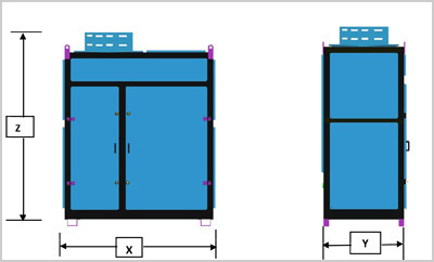
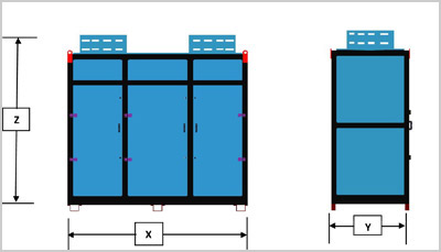
*(X), (Y), (Z) depends upon the Customer Technical Requirements.
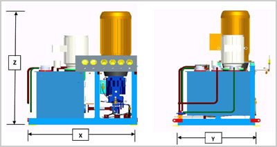
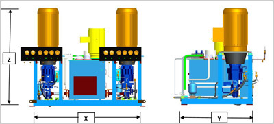
*(X), (Y), (Z) depends upon the Customer Technical Requirements.
Features of the HPU Power Unit
INCLUDED AS STANDARDS
- The Motor power range starting from 1.5Kw to 315kw Squirrel cage rotor, 4-pole electrical motor.
- Axial piston pump with electro hydraulic control.
- Fast pressure compensator, charge pump and flushing valve.
- Motor/pump set mounted on anti vibration pads.
- All internal pipe work and Wiring included.
- Oil tank, Air-oil cooler and water Solenoid valve.
- Temperatures switch with two switches and temperature indicator.
- Suction line valve with switch.
- Charge pressure switch.
- Oil filling point with quick release Connector.
- Electric junction box.
- Pressure gauges, Thermostat And Thermo well, Bi-Metal Thermo meter, Float Switch, Pressure Switch, Air Breather, Manifold Block
- Charge Pressure Filter, Return Line Filter
- Ball Valve, Suction valve, Hand Pump, Check Valve, Shuttle valve, Limit switch, Isolator Valve
- Pressure Gauge, Coupling, Pressure relief Valve, Accumulator(BladderType), Oil level Indicator, Anodized Circuit Plate
Choose the best method of your application
IMPROVING THE WORK ENVIRONMENT:
Six routines must be followed in order to minimize the chances of your hydraulic equipment suffering costly, premature component failures and unscheduled downtime:
The sound can be divided into three basic kinds:-
HYDRAULIC SYSTEM NOISES:-
Which focuses on the reduction of noise from individual component like hose, control valve, pump mounts and fixtures .This can be accomplished by a suitable design modification of the component so that it radiates least amount of noise.
Six routines must be followed in order to minimize the chances of your hydraulic equipment suffering costly, premature component failures and unscheduled downtime:
- Maintain fluid cleanliness.
- Maintain fluid temperature and viscosity with in optimum limits.
- Maintain hydraulic system settings to manufacturers' specifications
- Schedule component change - outs before they fail.
- Follow correct commissioning procedures.
- Conduct failure analysis.
The sound can be divided into three basic kinds:-
- Structured Borne Sound - (From the instance ofa pump)
- Air Borne Sounds - (From a Cooling FanorAiroil cooler.)
- Fluid Borne Sounds - (From Pump or Motor as pulsation in the oil flow).
HYDRAULIC SYSTEM NOISES:-
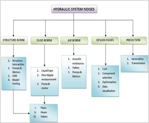
Which focuses on the reduction of noise from individual component like hose, control valve, pump mounts and fixtures .This can be accomplished by a suitable design modification of the component so that it radiates least amount of noise.
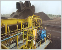
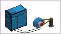
Example for an Installation:-